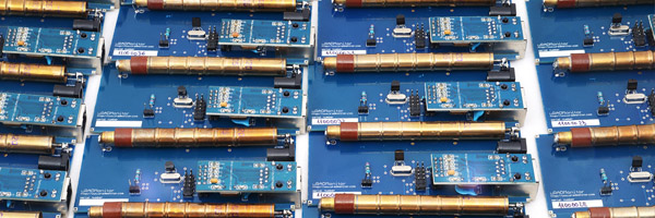
In an effort of expanding the network even further, several new units have been prepared and are ready to ship. But, creating a device that will function perfectly in a distributed environment is not an easy task. Yet, from its relatively early start, uRADMonitor has already spread to all major continents and continues to grow.

The entire process starts with the uRADMonitor circuit board, the most delicate and time consuming component. At the beginning of the project, manufacturing the PCBs was a laborious manual task. But now the preassembled PCBs with most components soldered are saving precious time. Even if produced in a specialised factory, the PCBs can still have issues, so they are carefully inspected, and any problems corrected. Finally, the Geiger Tubes are connected and so this step is completed.

Next, the software must be written into the microcontroller’s memory. The software is unique to each unit, because of the Device ID, allocated one for every unit. Using a programmer, the units are connected to a computer so the code can be downloaded. One at a time.

The units are then tested: network connectivity, sensor readings, inverter parameters, duty cycle safety limits, Geiger tube readings for background radiation and a fixed radioactive source. Usually 20% won’t work on first run, and corrections are needed. Sometimes bugs are hard to track: dead Geiger tubes, wrong value resistor in the voltage divider feedback circuit affecting the inverter output voltage, unsoldered pins/pads resulting in 0 radiation readings, or many other original and intriguing issues. Detecting the causes and correcting the problems takes time:


The Aluminium cases are composed of two metallic parts that join together and a rubber gasket to seal the top end and 4 screws on each side. Everything is mounted together:

The PCB is inserted, a small wooden piece is added to lock the PCB in place and the open lid is closed. Finally, a fully functional unit is ready.
A long run test of exposure to a fixed dose radiation source is started, while carefully paying attention to distance and geometry. The results are compared to a fixed reference. Any considerable differences will indicate an issue with the Geiger tube that would be replaced. Here is an example of measurements collected during one of these tests:

One colour corresponds to the unit under testing, while the other colour is the reference unit. The radiation source is placed symmetrically to the two. Obviously, the measurements must match.
By involving careful manufacturing and testing procedures, where enough time is allocated to every single unit, we can guarantee the consistency of the results provided by the uRADMonitor network. We believe this is a key feature of our technology, allowing direct comparison of the measurements presented, regardless of unit or location, giving us a clear indication on variations and their causes.


Hei.
Just a id: insted off make a unik code for every box, way don’t you just get the mac address for the ENC28J60 and use it as a uniq id ?
That way you can easy make use same software on all devices, update the code will be easy.
Hi Erik!
The enc28j60 modules don’t have a MAC address built in, the MAC address is configured from the microcontroller. But as it is now, the implementation is quite similar to what you have suggested, the unique device ID is extrapolated from the MAC address. It’s just that we still need to customise the code for each unit.
Hi All,
Just as a small tip, if you are using Dallas DS18… temerature sensor you can use their unique ID to identify your device.
But , I guess you’ve already considered this idea.
Regards,
Darko.
Hi Darko,
Actually I only thought about it a few weeks ago, while doing an upgrade on the DS18B20 code for the new firmware v112.
This is an excellent idea, however I will probably go for server-assigned IDs since I planned that already.
Thanks for the feedback though. Let me know if you spot any similar possible improvements!
Radu
hmmm how does 1 qualify to join in?